Building the Electronics for My A380 Overhead Panel (Part 1)

Introduction
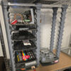
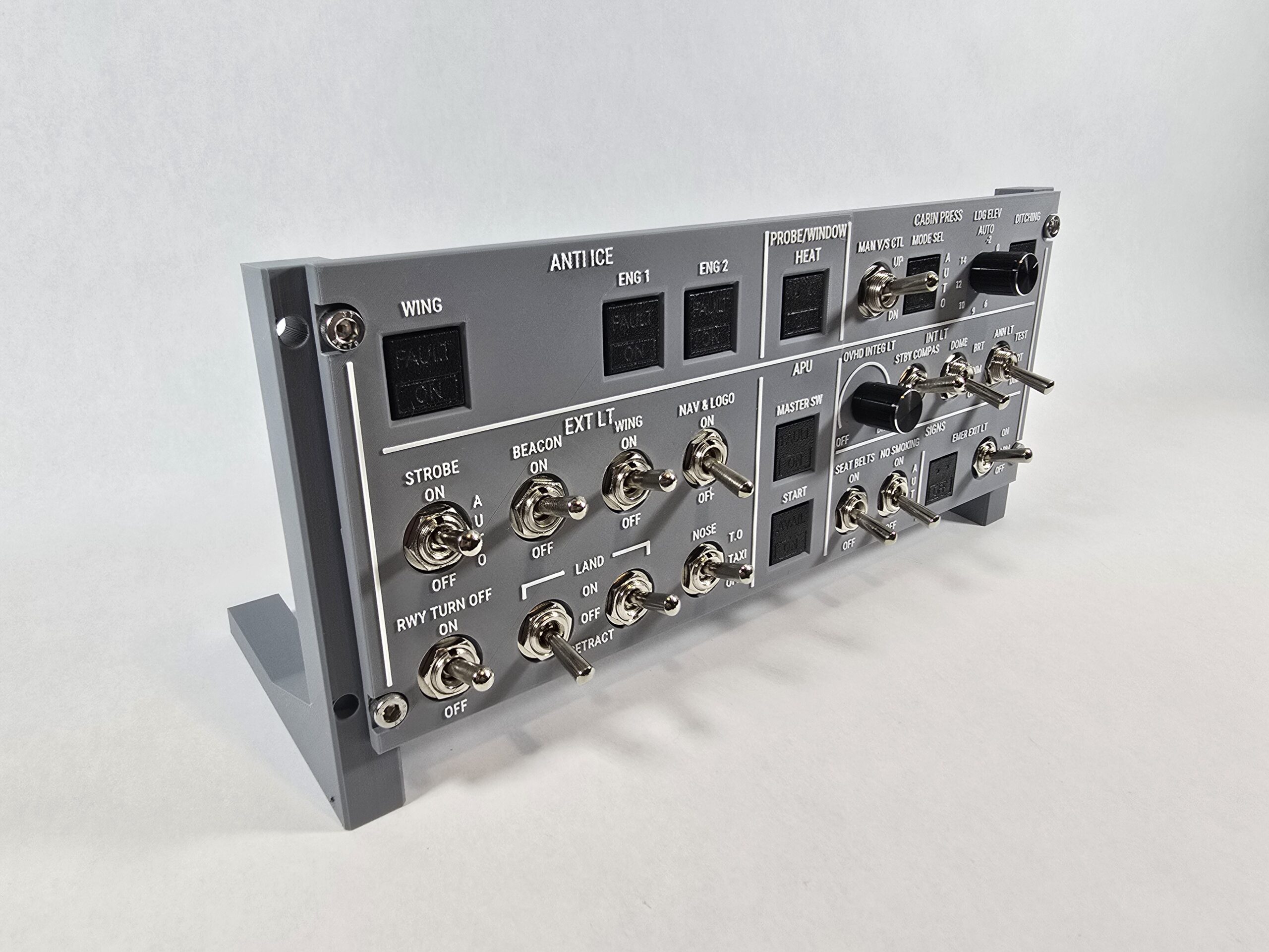
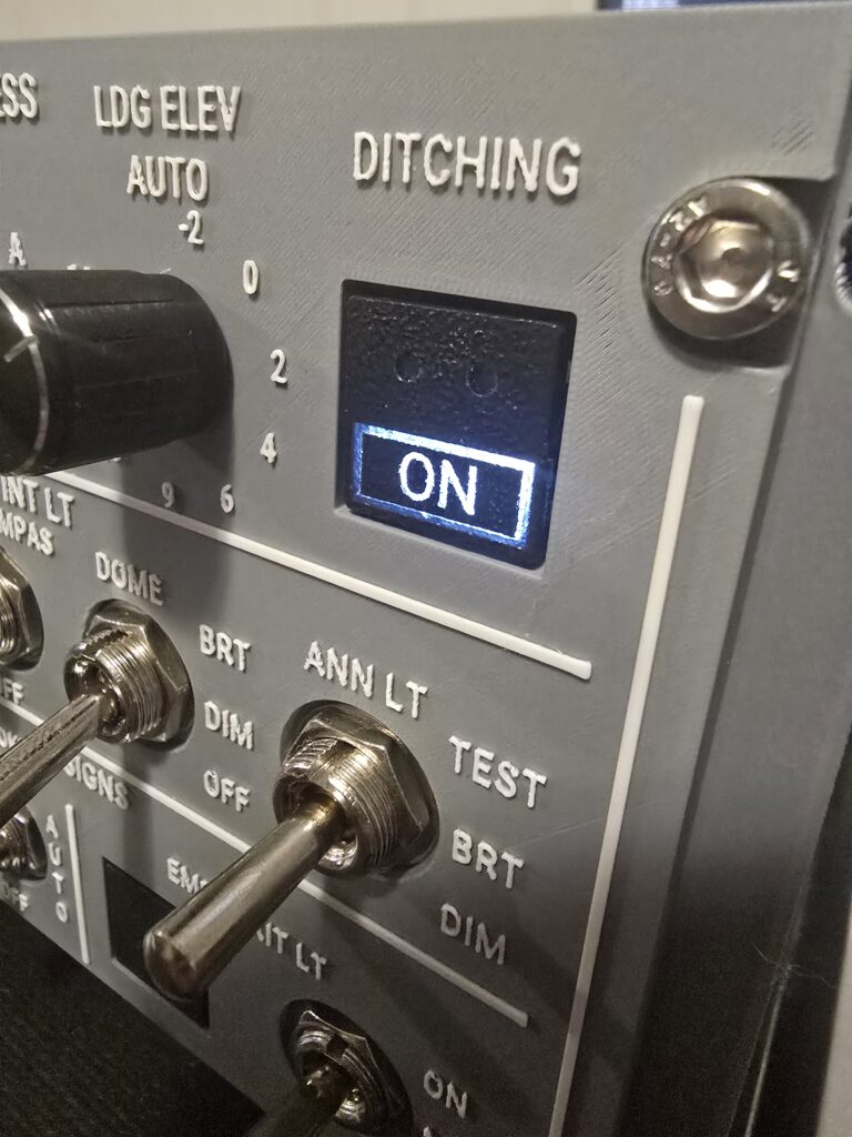
When I started building the Airbus A380 overhead panel for my simulator project, I quickly realized that the electronics would be just as complex as the physical build. The first panel I’m tackling is just one small section of the overall overhead, and even this piece already demands a surprising number of inputs and outputs. Each illuminated push-button switch (Korry-style) I designed and 3D-printed includes two LEDs and a momentary push-button—three I/O lines per switch. With nine of these switches in this section alone, plus potentiometers and a dozen toggle switches, the I/O requirements ballooned into the 50–60 range—well beyond what an Arduino Uno can handle directly.
That’s why I’m using the MCP23017 I²C I/O expander. It provides 16 extra GPIO per chip and lets me daisy-chain multiple expanders, so a single Arduino can manage the whole panel. Before scaling up, Step 1 was to prove that I could control one switch end-to-end: drive its LEDs and read its button, all through the MCP23017.
Step 1: Prove the concept with one switch
My switch pinout (top → bottom)
I forgot to label the silkscreen on these early Korry-style switches, so I mapped and verified the pin order. For reference, this is the layout:
- Top pin → Bottom LED
- Second pin → Top LED
- Third pin → Ground
- Fourth pin → Button (momentary)
This mapping is crucial and will be reused throughout the build.
Early struggles (and the fix)
At first, the Arduino’s I²C scanner couldn’t find the MCP23017 at all. I re-checked SDA/SCL, tied RESET high, strapped the address pins, and even slowed the bus—still nothing. The real culprit was that, for some reason, the IC wasn’t fully seating in the breadboard even with firm pressure. I simply moved it to another breadboard and it worked fine.
First working test
I was able to drive GPA5 and GPA6 to confirm both LEDs could be controlled. I wired the button to GPA7 with INPUT_PULLUP and confirmed presses by cycling three states:
- Bottom LED on, 2) Top LED on, 3) Both off, repeating on each press.
This validated both output control and input reading through the expander—exactly what I needed before scaling up.
What I used (minimal test rig)
- Arduino Uno (I²C on A4 = SDA, A5 = SCL)
- MCP23017 (bare DIP)
- VDD → 5V, VSS → GND
- RESET → 5V
- A0/A1/A2 → GND (I²C addr 0x20)
- 0.1 µF decoupling cap across VDD/VSS at the chip
- One illuminated push-button switch (Korry-style) wired per pinout above (LEDs via resistors)
Next Step: Chaining multiple MCP23017s
For this panel, one MCP23017 chip isn’t enough. I’m going to need a couple of these chained together, and fortunately, that turns out to be straightforward. The key is the three pins labeled A0, A1, and A2. These pins act as part of the chip’s I²C address. By wiring them high or low, each chip can be assigned a unique address on the same bus.
In my first setup, I tied A0, A1, and A2 all to ground, which gave that chip the address 0x20. For the second chip, I tied A0 high (to 5V) and left A1 and A2 grounded, which assigns it the address 0x21. With just that small change, the Arduino can now talk to both chips independently.
Aside from the address pins, all other wiring is exactly the same. Both chips share the same SDA and SCL lines (tied to A4 and A5 on the Arduino), both need VDD to 5V and VSS to ground, and both have RESET tied high. You can tie them together at the rails or run separate wires; electrically it’s the same.
For this test, I reused GPA5, GPA6, and GPA7 on the second chip, wiring them to another illuminated push-button switch. The code was adjusted to create a second MCP23017 instance at the new address, and each button now drives its own LEDs independently.
The result: it was actually pretty easy. Both chips work, I can interact with each individually, and they don’t interfere with each other at all. Even when I tap both buttons quickly or nearly simultaneously, everything behaves reliably. This proof-of-concept confirms that scaling out with multiple expanders is going to be practical for the full overhead panel.